How computer-aided design transforms innovative ideas into manufacturable products
Bringing a product idea to life requires precision, iteration and visualisation that traditional sketching cannot always provide. CAD for product design is a cornerstone of modern innovation. It enables designers and engineers to turn abstract concepts into detailed prototypes with confidence. It also helps test functionality and communicate intent across the entire product development team.
The journey from initial sketch to finished prototype involves multiple stages, each demanding clarity and control. Parametric modelling in CAD platforms lets designers adjust dimensions dynamically. This ensures changes propagate logically through the entire assembly. This flexibility accelerates iteration cycles and reduces costly errors during the transition to physical production. Digital simulations of real-world conditions reveal flaws early. Designers identify and correct flaws before material is cut or moulded. This minimizes waste and accelerates production.
Why CAD for Product Design is Essential in Modern Development
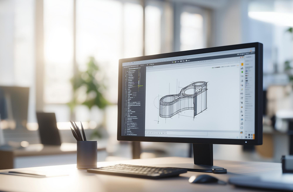
Product design has evolved beyond pen and paper. CAD for product design now underpins the workflows of industry leaders worldwide. The software enables three-dimensional visualisation from the earliest stages, allowing stakeholders to see and understand the proposed product long before prototyping begins. This clarity improves communication between design teams, marketing departments and manufacturing partners, ensuring everyone shares the same vision.
Design intent is captured through parametric relationships and constraints, meaning that when one dimension changes, related features update automatically. This intelligent behaviour prevents the manual recalculation that plagued earlier design methods and reduces human error significantly. Engineers can explore multiple design variants rapidly, comparing performance characteristics and cost implications without rebuilding the model from scratch each time.
Integration with analysis tools adds another layer of value. Analysts perform finite element analysis, CFD, and thermal simulations within or beside the CAD environment, yielding performance feedback. These insights guide refinement, ensuring that the final design not only looks right but performs reliably under expected operating conditions.
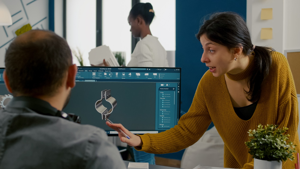
Collaboration across geographies is simplified through cloud-based CAD platforms. Teams can work on the same assembly concurrently, with version control preventing conflicts and maintaining a clear audit trail. This distributed approach accelerates project timelines and allows organisations to tap into specialised talent regardless of physical location, making global product development both practical and efficient.
The CAD for Product Design Workflow: From Sketch to Digital Model
The typical workflow begins with concept sketches or mood boards that capture the desired aesthetic and functional requirements. These early visuals are then translated into rough 3D forms using basic primitives and surface tools. At this stage, the focus is on proportion and overall form rather than fine detail. Designers often produce multiple variations to explore different approaches before committing to a single direction.
When a concept is selected, we refine the model with precise dimensions, tolerances, and material specifications. Parametric features such as extrusions, revolves and lofts are employed to create complex geometry efficiently. Fillets, chamfers and surface blends are added to improve manufacturability and aesthetic appeal. The model now transitions from a conceptual representation to a detailed design that can be scrutinized for engineering feasibility.
Building Assemblies and Validating Fit
Designers assemble components into assemblies, using mates and constraints to define their spatial relationships. This assembly environment allows designers to check for interferences, validate clearances and ensure that moving parts operate without collision. Motion studies can simulate mechanisms such as hinges, gears and linkages, revealing potential binding or misalignment issues that might not be obvious from static views.
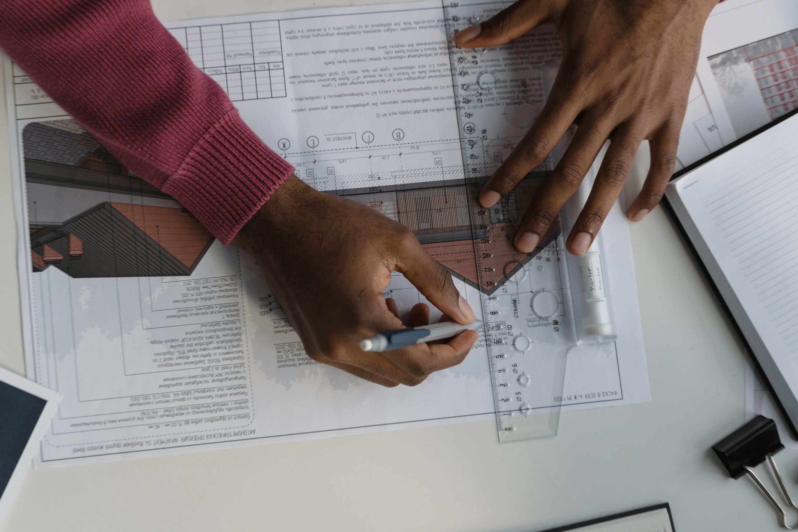
The CAD model generates documentation directly. The system automatically produces technical drawings with orthographic projections, sectional views, and detailed annotations, maintaining consistency with the 3D geometry. This eliminates discrepancies between drawings and models, a common source of manufacturing errors in older workflows.
Tip: Establish clear naming conventions and file structures at the project’s outset. Consistent organisation prevents confusion when assemblies grow large and multiple team members are contributing components. Use descriptive part names and revision markers to maintain clarity throughout the development cycle.
Prototyping and Manufacturing Preparation with CAD for Product Design
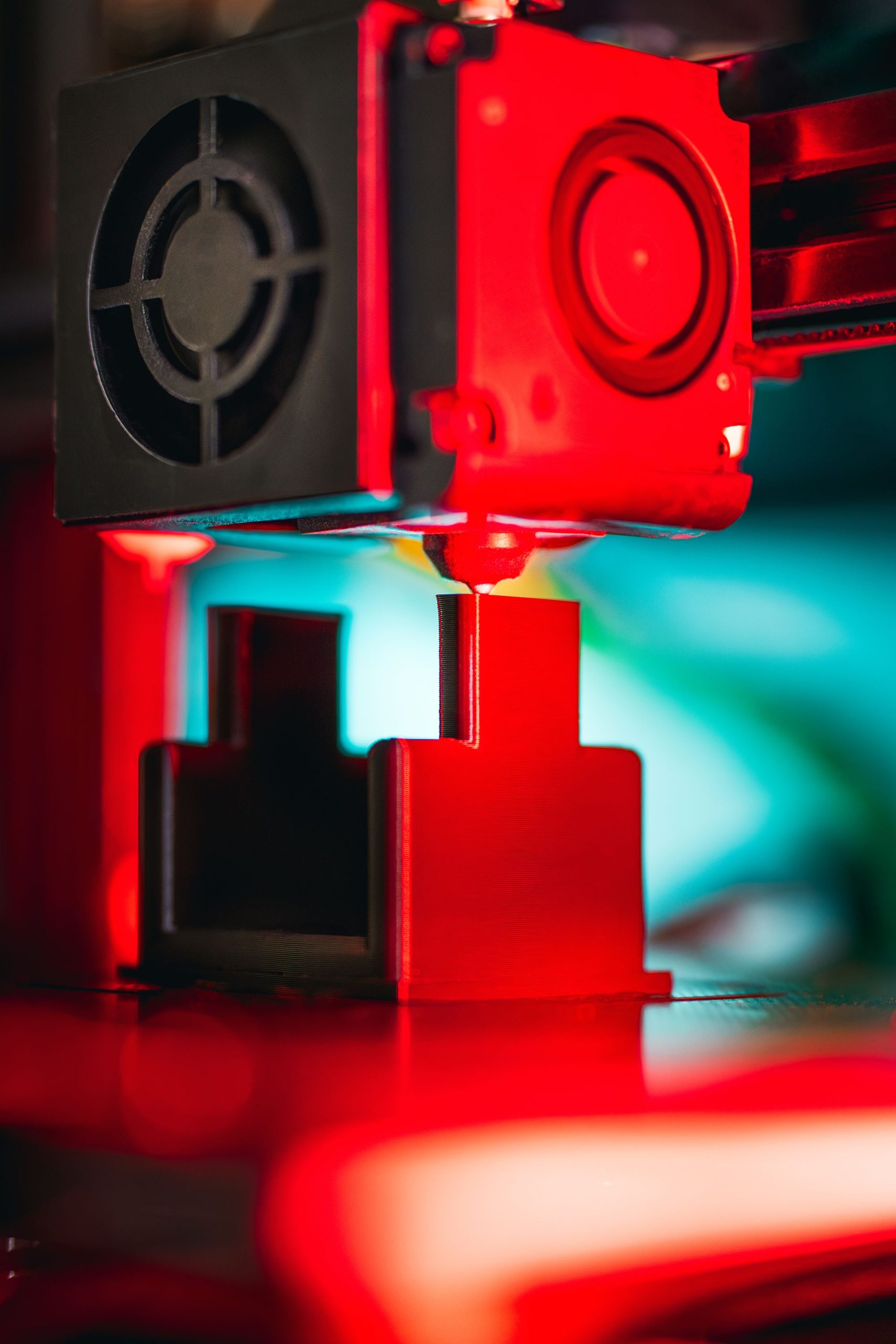
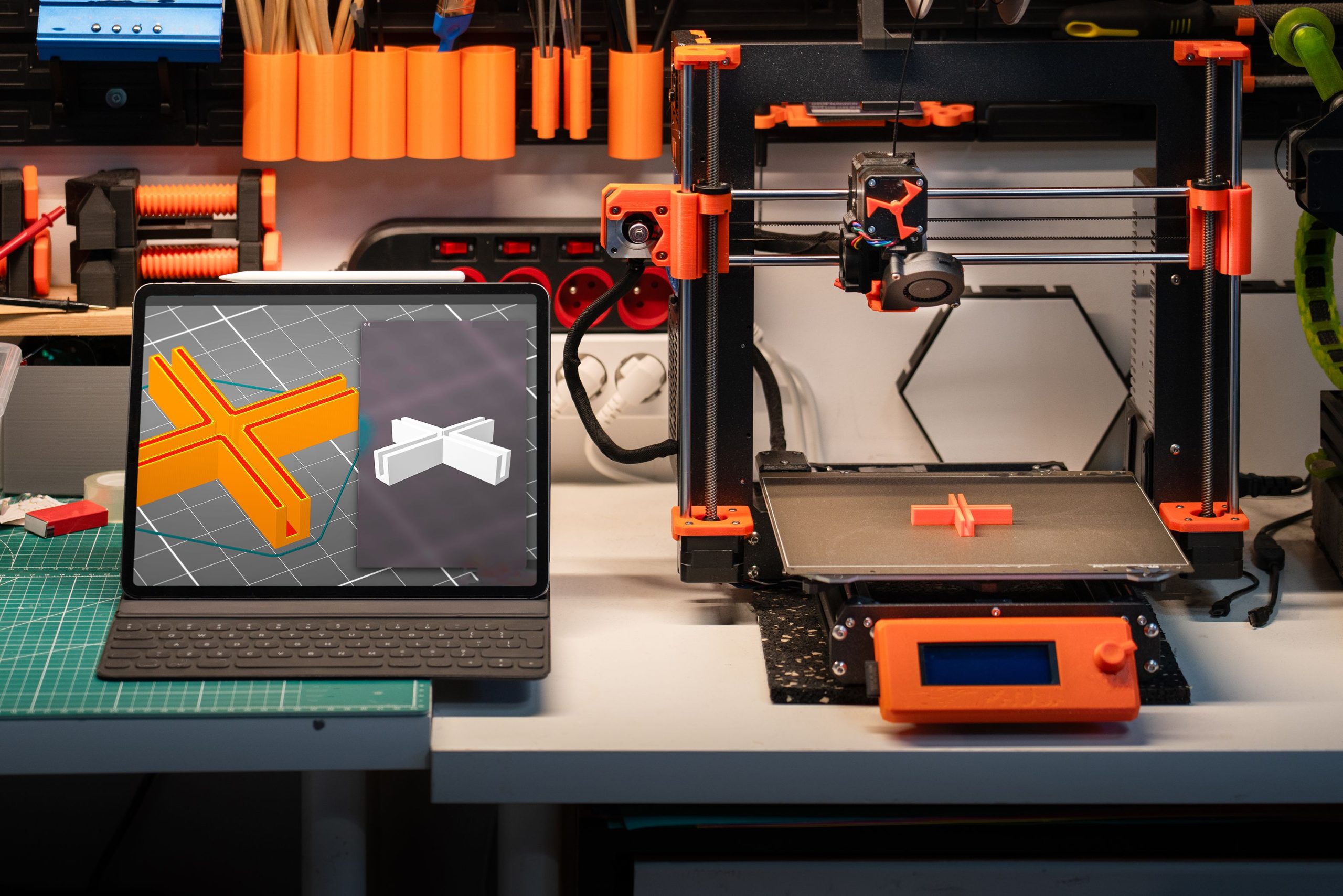
Once the digital model is validated, it serves as the foundation for physical prototyping. Additive manufacturing technologies such as 3D printing allow rapid production of prototype parts directly from the CAD file, enabling tactile evaluation and user testing within days. Designers can assess ergonomics, identify assembly challenges and gather stakeholder feedback with physical models that closely resemble the intended final product.
For higher-fidelity prototypes, CNC machining and injection moulding tooling paths are generated from the same CAD geometry. The precision of the digital model ensures that manufactured parts match the design intent, reducing the need for manual rework and expediting the path to production readiness. Surface finish, draft angles and undercuts are all considered during the CAD phase, ensuring that the design can be manufactured economically and reliably.
Material selection is informed by simulation results embedded in the CAD workflow. If stress analysis reveals excessive deflection, the designer can switch to a stiffer material or adjust wall thicknesses within the model. Cost estimation tools can compare different manufacturing processes, helping decision-makers balance performance against budget constraints. This data-driven approach to prototyping reduces waste and shortens the time from concept to market launch.
Communication with manufacturing partners is streamlined when CAD models are shared in standardised formats such as STEP or IGES. These neutral files preserve geometric accuracy while remaining accessible to a wide range of downstream software, from CAM systems to inspection equipment. The seamless transfer of data minimises translation errors and ensures that what was designed is what gets built.
Choosing the Right Tools and Skills for Effective Product Design
Selecting appropriate CAD software depends on the complexity of the product, the size of the team and the intended manufacturing methods. Some platforms excel at organic surface modelling, ideal for consumer products with flowing aesthetics, while others prioritise mechanical assemblies with tight tolerances and extensive part libraries. Evaluating trial versions and seeking recommendations from industry peers can guide this decision.
Skill development is an ongoing requirement. Understanding the fundamentals of computer-aided design provides a strong foundation, but mastering advanced techniques such as surfacing, sheet metal design and parametric optimisation requires dedicated practice. Many professionals pursue formal training courses, online tutorials or mentorship from experienced designers to deepen their expertise and stay current with evolving software capabilities.
Integrating CAD for product design into a broader product lifecycle management system enhances efficiency further. PLM platforms manage revisions, approvals and change orders, ensuring that the most current design data is always available to all stakeholders. This holistic approach reduces duplication of effort and maintains a single source of truth throughout the product’s lifecycle, from initial concept through to end-of-life considerations.
Collaboration between industrial designers and mechanical engineers is critical. Designers focus on aesthetics, user experience and brand alignment, while engineers ensure structural integrity, thermal performance and manufacturability. CAD software serves as the common language, allowing both disciplines to contribute their expertise within a unified digital model. Regular design reviews and cross-functional workshops foster this collaboration and lead to better, more balanced product outcomes.