A professional guide to transforming ideas into tangible prototypes through computer-aided design
Published: 7 October 2026 | 6 min read
TL;DR
- Use CAD to turn ideas into manufacturable products—from early concepts through to physical prototypes.
- Explore multiple concepts early rather than over-perfecting one design; parametric CAD makes changes and iterations faster.
- Build with manufacturing in mind, considering tolerances, materials, assembly, tooling and production methods as the design develops.
- Use digital prototyping and simulation to test strength, heat, movement and potential failures before spending money on physical prototypes.
- Prepare CAD files carefully for manufacturing, checking geometry, file formats, tolerances and other process-specific requirements.
- Keep drawings and documentation up to date alongside the CAD model so manufacturers have clear specifications.
- Communicate with manufacturers early to confirm file compatibility, tolerances, finishes, quantities and potential costs.
- The key takeaway: effective CAD workflows reduce costly redesigns, speed up development and make the transition from concept to prototype much smoother.
The journey from an initial product idea to a working prototype demands precision, iteration and clear communication across design teams. CAD for product design has become the essential tool that bridges imagination and manufacturing, enabling designers to visualize, test and refine their concepts long before committing to physical production. This technology reduces development costs, accelerates time-to-market and minimizes the risk of costly errors during manufacture.
Whether you’re developing consumer electronics, medical devices, automotive components or industrial equipment, understanding how to leverage CAD effectively throughout the product development lifecycle determines the difference between a smooth launch and a series of expensive revisions. This guide examines the complete workflow from conceptual sketches through to prototype-ready models, highlighting the decisions and techniques that separate efficient product development from inefficient iteration.
CAD for Product Design: Establishing Your Initial Concept
Every successful product begins with a clear concept that balances user needs, manufacturing constraints and business objectives. The initial phase of using CAD for product design involves translating rough sketches and requirements documents into preliminary three-dimensional geometry. Most designers begin with simple primitive shapes—cylinders, boxes, spheres—to establish overall proportions and spatial relationships before adding detail.
At this stage, accuracy takes second place to exploration. Create multiple concept variants quickly rather than perfecting a single design too early. Modern parametric CAD systems allow you to define dimensions and relationships that can be adjusted globally, meaning a change to one measurement automatically updates dependent features throughout the model. This parametric approach proves invaluable when stakeholders request modifications or when manufacturing feedback requires dimensional adjustments.
Document your design intent clearly within the CAD model itself using comments, named features and organized model trees. When you return to a project weeks later, or when colleagues need to understand your approach, this documentation ensures continuity. Many designers also maintain a simple design journal alongside their CAD files, noting why certain decisions were made and what constraints influenced the form. This practice becomes particularly valuable during design reviews when justifying choices to clients or internal stakeholders.
Choosing the Right CAD Environment
Selecting appropriate software for your product design work depends on the complexity of your geometry, your team’s existing skills and your downstream manufacturing processes. Solid modeling systems excel at mechanical components with precise tolerances, while surface modeling tools offer greater freedom for organic forms. Some products require hybrid approaches, combining both techniques within the same model. Evaluate whether your work demands simulation capabilities, rendering quality or specialized toolsets for sheet metal, injection molding or other manufacturing methods.
Developing Design Detail and Engineering Features
Once the overall concept gains approval, the next phase involves adding the engineering detail that transforms an attractive shape into a manufacturable product. This stage incorporates fasteners, assembly interfaces, material considerations and production methods into your CAD model. Designers must think simultaneously about form, function and fabrication—a beautiful design that cannot be manufactured economically serves no purpose.
Begin by defining assembly relationships and tolerances. Determine which components move, which remain fixed, and how parts connect to one another. CAD assemblies allow you to verify clearances, check for interference and simulate motion before any physical parts exist. Pay particular attention to areas where multiple components meet, as these junctions often expose design conflicts that appear only when viewed in three dimensions.
Material selection profoundly influences your CAD modeling approach. Plastic components designed for injection molding require uniform wall thickness, appropriate draft angles for mold release and strategic placement of ribs for strength without excessive material. Metal parts destined for CNC machining demand consideration of tool access, cutting forces and economical stock sizes. Understanding these manufacturing constraints while still in the CAD environment prevents expensive redesigns later. Many CAD systems include design-for-manufacture analysis tools that flag potential production issues before you export files for quotation.
Professional Tip: Maintain separate configurations or versions of your CAD models for different purposes. Your marketing team may need simplified geometry for renderings, while manufacturing requires complete technical detail including internal features. Version control becomes critical as designs evolve—label files clearly with dates and revision numbers to prevent confusion during production.
CAD for Product Design: Validation Through Digital Prototyping
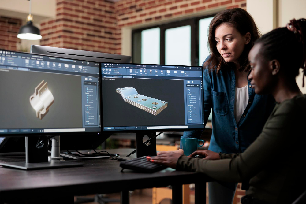
Digital prototyping represents one of the most valuable capabilities that CAD for product design delivers to modern development teams. Before investing in physical tooling or manufacturing, you can subject your design to rigorous testing within the virtual environment. Finite element analysis evaluates structural performance under load, thermal simulation predicts heat dissipation, and motion studies verify that mechanisms operate as intended throughout their range of travel.
These simulation capabilities require accurate material properties, appropriate boundary conditions and realistic loading scenarios. Invest time in setting up your analyses correctly—poorly configured simulations generate misleading results that can lead to design decisions worse than no simulation at all. When simulation predicts potential failures or performance shortfalls, iterate your design within the CAD environment rather than discovering problems during physical testing. Each digital iteration costs only time, whereas physical prototypes consume materials, manufacturing capacity and schedule.
Collaboration improves dramatically when stakeholders can interact with three-dimensional models rather than interpreting two-dimensional drawings. Export your CAD data to formats suitable for virtual reality walkthroughs, augmented reality reviews or simple web-based viewers that require no specialized software. Professional CAD services often include visualization and presentation support, ensuring your design communicates effectively to technical and non-technical audiences alike. Clear communication during design reviews prevents misunderstandings that lead to expensive changes during production.
Preparing Files for Physical Prototype Manufacturing
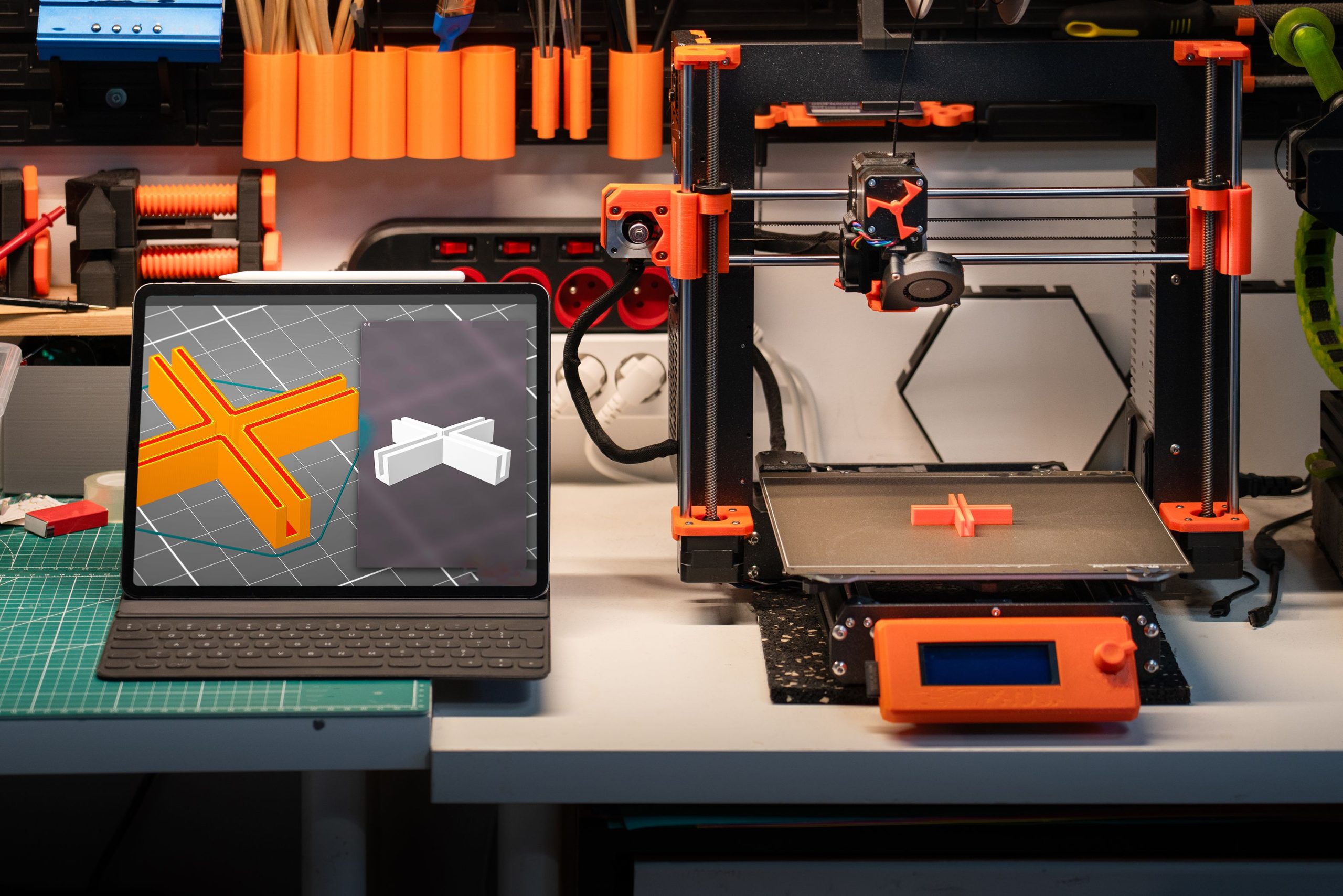
The transition from CAD model to physical prototype requires careful preparation of your digital files for the chosen manufacturing process. Different prototyping methods demand different file formats and modeling approaches. Additive manufacturing processes like 3D printing typically require watertight mesh files exported as STL or 3MF formats, with appropriate consideration for support structures and build orientation. Subtractive processes like CNC machining work from solid models supplemented with toolpath programming, often requiring additional manufacturing detail not present in the design model itself.
Review your CAD geometry for issues that may not be apparent on screen but cause problems during manufacture. Small gaps between surfaces, duplicate geometry, or features smaller than the manufacturing process can resolve will halt production or result in defective parts. Most CAD systems include validation tools that check models against common manufacturing criteria, highlighting potential issues before you export files. Address these warnings systematically rather than hoping they prove inconsequential—they usually do not.
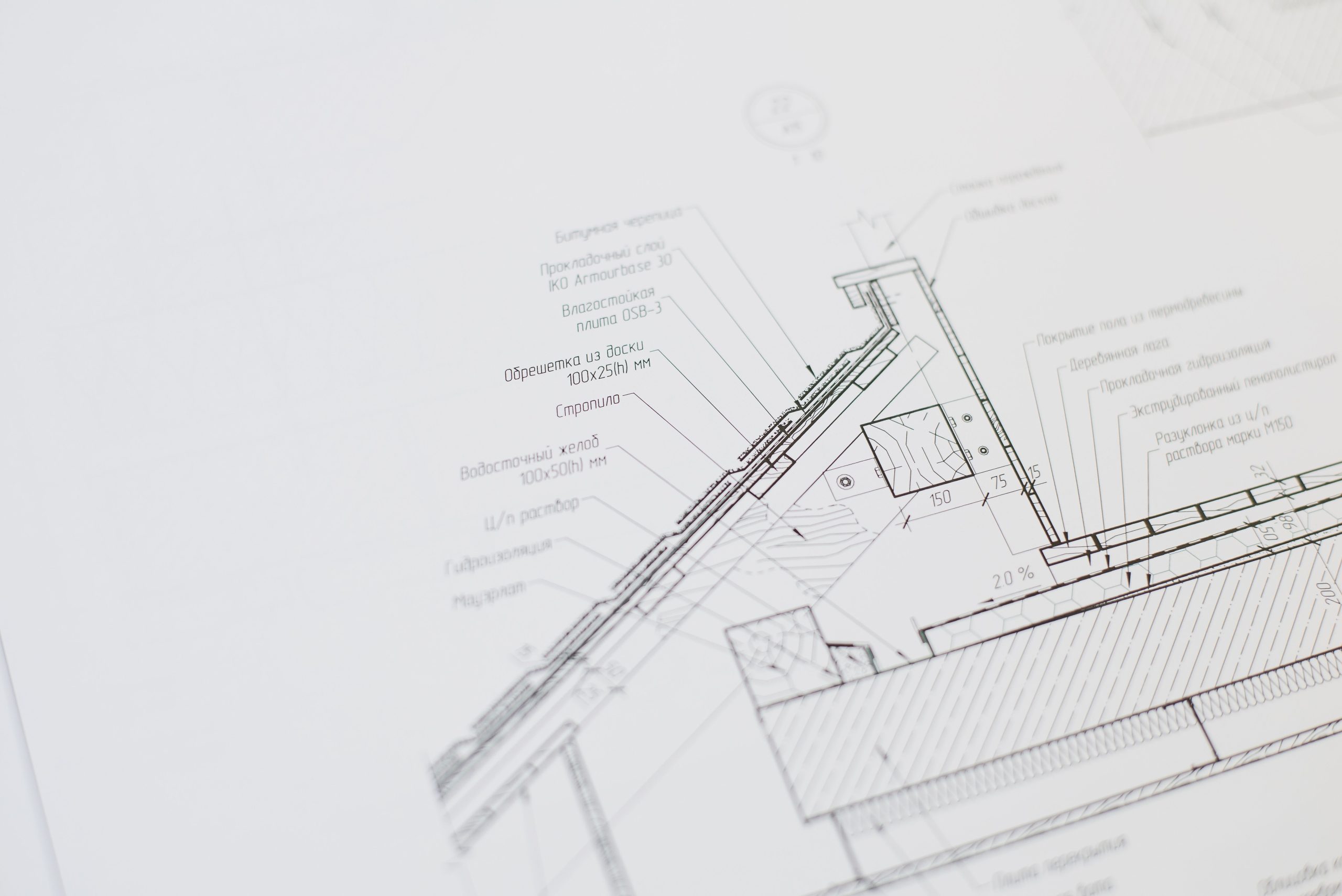
Dimensioned drawings remain essential even in an era of three-dimensional CAD data. Manufacturers need explicit specifications for critical dimensions, tolerances, surface finishes and material requirements. Create detailed drawings that complement your CAD models, calling out which features matter most for fit and function. When prototyping reveals that certain dimensions require adjustment, update both your CAD model and associated drawings to maintain consistency. This discipline ensures that when you transition from prototype to production, your documentation accurately reflects the validated design.
Communication with your prototype manufacturer before finalizing files prevents delays and unexpected costs. Share your CAD data early to confirm compatibility with their systems and processes. Discuss tolerances, finish requirements and quantities openly—prototyping often involves different economic considerations than production manufacturing. Some features may prove expensive or difficult to prototype but straightforward to produce at scale, while others follow the opposite pattern. Understanding these nuances helps you make informed decisions about what to validate during prototyping and what to defer until production tooling.